OSを使わない素のプログラムをBeagleBone上で走らせるため、Code Composer Studio(CCS)+JTAG+BeagleBoneの組み合わせで接続してみた。結論は接続テストはOKだけど、デバッグ実行でエラーが出る。これは、jtagで不適切な領域に書こうとしたからか??
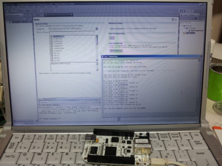
 動作テストした環境。ノートPC+CCS、USBケーブル経由で接続したBeagleBone..
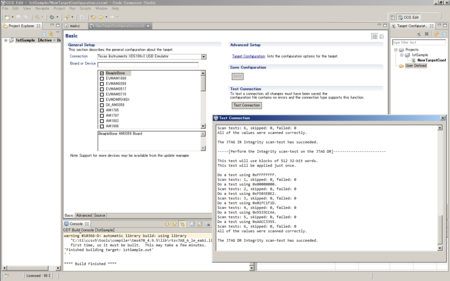
 (PC+CCS)->USBケーブル->BeagleBoneの組み合わせで接続セットアップ実施。debugセットアップダイアログ(Target Configuration)で以下を設定
- Connection: Texas Instruments XDS100v2 USB Emulator
- Board or Device: [x] BeagleBone
上記設定して、保存後、接続テストを実行すると、正常応答
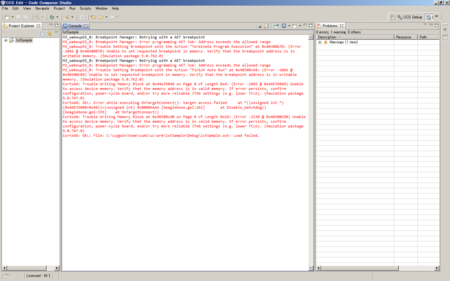
 気をよくしてデバッグボタンを押下。ブレーク設定できないといったエラーとダウンロード失敗エラーが出る。生成コードのマップを見ると以下に配置しようとしている。
AM3359.cmdを見ると、L3OCMC0とは内蔵RAM?
L3OCMC0 40300000
エラーメッセージは以下
L3OCMC0: o = 0x40300000 l = 0x00010000 /* 64kB L3 OCMC SRAM */
CortxA8: Trouble Writing Memory Block at 0x44e35048 on Page 0 of Length 0x4: (Error -1065 @ 0x44E35048) Unable to access device memory. Verify that the memory address is in valid memory. If error persists, confirm configuration, power-cycle board, and/or try more reliable JTAG settings (e.g. lower TCLK). (Emulation package 5.0.747.0)
CortxA8: GEL: Error while executing OnTargetConnect(): target access failed 	at *((unsigned int *) (0x44E35000+0x48))=(unsigned int) 0x0000AAAA [beaglebone.gel:262] 	at Disable_Watchdog() [beaglebone.gel:335] 	at OnTargetConnect() .
CortxA8: Trouble Writing Memory Block at 0x40300ce8 on Page 0 of Length 0x24: (Error -2130 @ 0x40300CE8) Unable to access device memory. Verify that the memory address is in valid memory. If error persists, confirm configuration, power-cycle board, and/or try more reliable JTAG settings (e.g. lower TCLK). (Emulation package 5.0.747.0)
CortxA8: GEL: File: C:\cygwin\home\sumi\ti_test\test\Debug\test.out: Load failed.
不明点
- 0x44E35000とはいったい誰が指定したアドレスなのか? OnTargetConnect()でじかがきされている?
■追記
メッセージ、Disable_Watchdog() [beaglebone.gel:335] より、該当箇所を調査
file:c:/ti/ccsv5/ccs_base/emulation/boards/beaglebone/gel/beaglebone.gel

L:335
  Disable_Watchdog();
L:378
  Disable_Watchdog()
  {
      WR_MEM_32(WDT1_WSPR,0x0000AAAA); <<<< エラー発生箇所
      WR_MEM_32(WDT1_WSPR,0x00005555);
  }

//*******************************************************************
//Watchdog Timer registers
//*******************************************************************
#define    WDT1_BASE_ADDR                                        (0x44E35000)
#define WDT1_WSPR (WDT1_BASE_ADDR + 0x48)ハード上、ここにWDTのレジスタは存在するのか。。
AM3359のハードウエア仕様書を読む限り、WDT_WSPRの番地は正しいようだ。
■追記 (2012/9/30)
書けないというのは実は違っていて、書いた値が正しく反映されないとか、別の値に変わってしまうとかそういうことでは?と推測して、JTAGで接続する直前までLinuxが走っているので、LinuxでもWDTを操作しているのでは?と想像した。そこで、SDカードを抜いてブートローダだけ動いている状態でJTAGを接続してみた。すると、エラーなく接続できた。上記のエラーは、デバッグ準備ステップとLinuxの稼動が衝突したためではないか?と言う事で自分を納得させる。。以下は正常にセットアップできたときのメッセージ
CortxA8: Output: ****  AM335x 15x15 EVM Initialization is in progress ..........
CortxA8: Output: ****  AM335x ALL PLL Config for OPP == OPP100 is in progress .........
CortxA8: Output: Input Clock Read from SYSBOOT[15:14]:  24MHz
CortxA8: Output: ****  Going to Bypass...
CortxA8: Output: ****  Bypassed, changing values...
CortxA8: Output: ****  Locking ARM PLL
CortxA8: Output: ****  Core Bypassed
CortxA8: Output: ****  Now locking Core...
CortxA8: Output: ****  Core locked
CortxA8: Output: ****  DDR DPLL Bypassed
CortxA8: Output: ****  DDR DPLL Locked
CortxA8: Output: ****  PER DPLL Bypassed
CortxA8: Output: ****  PER DPLL Locked
CortxA8: Output: ****  DISP PLL Config is in progress ..........
CortxA8: Output: ****  DISP PLL Config is DONE ..........
CortxA8: Output: ****  AM335x ALL ADPLL Config for OPP == OPP100 is Done .........
CortxA8: Output: ****  AM335x DDR2 EMIF and PHY configuration is in progress.........
CortxA8: Output: EMIF PRCM is in progress .......
CortxA8: Output: EMIF PRCM Done
CortxA8: Output: DDR PHY Configuration in progress
CortxA8: Output: Waiting for VTP Ready .......
CortxA8: Output: VTP is Ready!
CortxA8: Output: DDR PHY CMD0 Register configuration is in progress .......
CortxA8: Output: DDR PHY CMD1 Register configuration is in progress .......
CortxA8: Output: DDR PHY CMD2 Register configuration is in progress .......
CortxA8: Output: DDR PHY DATA0 Register configuration is in progress .......
CortxA8: Output: DDR PHY DATA1 Register configuration is in progress .......
CortxA8: Output: EMIF Timing register configuration is in progress .......
CortxA8: Output: EMIF Timing register configuration is done .......
CortxA8: Output: DDR PHY Configuration done
CortxA8: Output: ****  AM335x DDR2 EMIF and PHY configuration is done ****
CortxA8: Output: ****  AM335x 15x15 EVM Initialization is Done ******************
以下のような素のサンプル(メインループだけ)に対してステップ実行が行えた。なお、コードはデフォルトではARMの内蔵メモリ領域に配置されるようである(0x40300CB4 前後)。ループが実行できたので、お次は評価ボードではお決まりのLEDチカチカをやってみる予定。。
CCSはフラッシュ領域にも書き込みができるようで*1、本当にflash書き込み機能が使えるなら、CCSが一番良くできたツールではないかと思える。有償だけど。。一体いくらなのか!?
main()

{

    int i=0;

    while(1){

         i++;

    }

}
■参考URL
Code Composer Studio v5
http://processors.wiki.ti.com/index.php/Category:Code_Composer_Studio_v5
CCSによるBeagleBoneに対するデバッグ
http://processors.wiki.ti.com/index.php/FAQ_-_CCSv5#Debugging
CCS download site
http://processors.wiki.ti.com/index.php/Download_CCS
CCSからJTAG経由でBeagleBoneにつなぐ方法
http://e2e.ti.com/support/development_tools/code_composer_studio/f/81/t/185703.aspx
CCSからJTAG経由でBeagleBoneのu-bootをデバッグする方法
http://e2e.ti.com/support/development_tools/code_composer_studio/f/81/t/185758.aspx
CCS(V5)とBeagleBoneが繋がらないという事例
http://processors.wiki.ti.com/index.php/FAQ_-_CCSv5#Q:_I_can.27t_connect_to_my_BeagleBone_in_CCSv5._What_is_happening.3F
XDS100に関するWiki
http://processors.wiki.ti.com/index.php/XDS100
Debugging JTAG Connectivity Problems(TI CSS Wiki)
http://processors.wiki.ti.com/index.php/Debugging_JTAG_Connectivity_Problems
Troubleshooting CCSv5
http://processors.wiki.ti.com/index.php/Troubleshooting_CCSv5
■追加情報
JTAG接続試験の結果(試験は通過)
[Start]
Execute the command:
%ccs_base%/common/uscif/dbgjtag -f %boarddatafile% -rv -o -F inform,logfile=yes -S pathlength -S integrity

[Result]


-----[Print the board config pathname(s)]------------------------------------

C:\Users\FOO\AppData\Local\.TI\213602635\
    0\0\BrdDat\testBoard.dat

-----[Print the reset-command software log-file]-----------------------------

This utility has selected a 100- or 510-class product.
This utility will load the adapter 'jioserdesusb.dll'.
The library build date was 'May 30 2012'.
The library build time was '22:52:27'.
The library package version is '5.0.747.0'.
The library component version is '35.34.40.0'.
The controller does not use a programmable FPGA.
The controller has a version number of '4' (0x00000004).
The controller has an insertion length of '0' (0x00000000).
This utility will attempt to reset the controller.
This utility has successfully reset the controller.

-----[Print the reset-command hardware log-file]-----------------------------

The scan-path will be reset by toggling the JTAG TRST signal.
The controller is the FTDI FT2232 with USB interface.
The link from controller to target is direct (without cable).
The software is configured for FTDI FT2232 features.
The controller cannot monitor the value on the EMU[0] pin.
The controller cannot monitor the value on the EMU[1] pin.
The controller cannot control the timing on output pins.
The controller cannot control the timing on input pins.
The scan-path link-delay has been set to exactly '0' (0x0000).

-----[The log-file for the JTAG TCLK output generated from the PLL]----------

There is no hardware for programming the JTAG TCLK frequency.

-----[Measure the source and frequency of the final JTAG TCLKR input]--------

There is no hardware for measuring the JTAG TCLK frequency.

-----[Perform the standard path-length test on the JTAG IR and DR]-----------

This path-length test uses blocks of 512 32-bit words.

The test for the JTAG IR instruction path-length succeeded.
The JTAG IR instruction path-length is 6 bits.

The test for the JTAG DR bypass path-length succeeded.
The JTAG DR bypass path-length is 1 bits.

-----[Perform the Integrity scan-test on the JTAG IR]------------------------

This test will use blocks of 512 32-bit words.
This test will be applied just once.

Do a test using 0xFFFFFFFF.
Scan tests: 1, skipped: 0, failed: 0
Do a test using 0x00000000.
Scan tests: 2, skipped: 0, failed: 0
Do a test using 0xFE03E0E2.
Scan tests: 3, skipped: 0, failed: 0
Do a test using 0x01FC1F1D.
Scan tests: 4, skipped: 0, failed: 0
Do a test using 0x5533CCAA.
Scan tests: 5, skipped: 0, failed: 0
Do a test using 0xAACC3355.
Scan tests: 6, skipped: 0, failed: 0
All of the values were scanned correctly.

The JTAG IR Integrity scan-test has succeeded.

-----[Perform the Integrity scan-test on the JTAG DR]------------------------

This test will use blocks of 512 32-bit words.
This test will be applied just once.

Do a test using 0xFFFFFFFF.
Scan tests: 1, skipped: 0, failed: 0
Do a test using 0x00000000.
Scan tests: 2, skipped: 0, failed: 0
Do a test using 0xFE03E0E2.
Scan tests: 3, skipped: 0, failed: 0
Do a test using 0x01FC1F1D.
Scan tests: 4, skipped: 0, failed: 0
Do a test using 0x5533CCAA.
Scan tests: 5, skipped: 0, failed: 0
Do a test using 0xAACC3355.
Scan tests: 6, skipped: 0, failed: 0
All of the values were scanned correctly.

The JTAG DR Integrity scan-test has succeeded.

[End]